
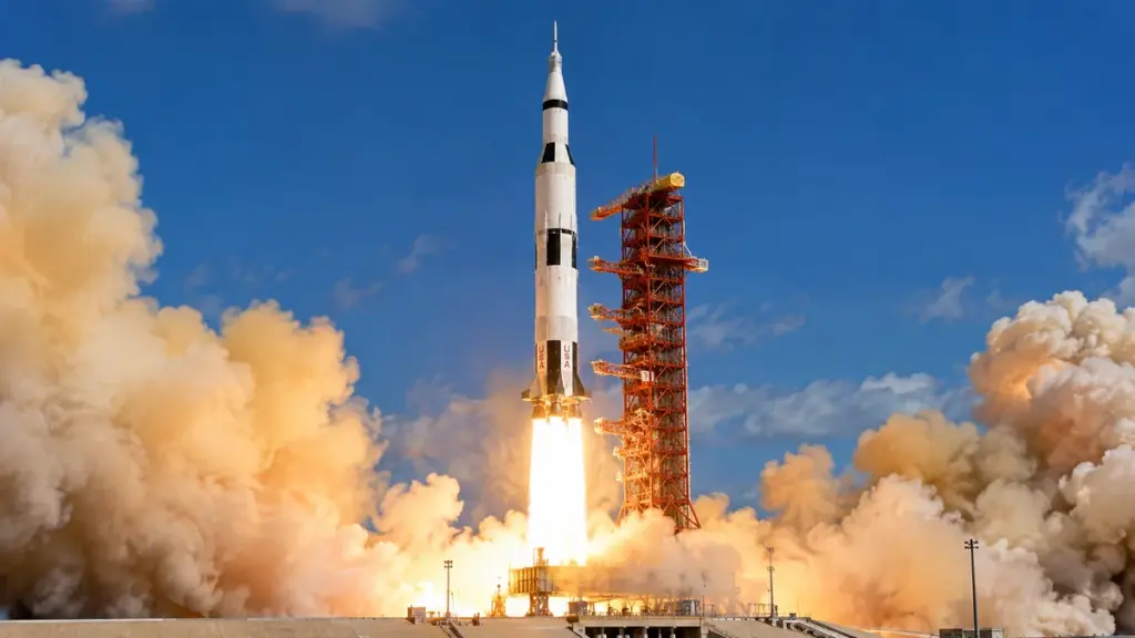
The Saturn V rocket was one of the most extraordinary engineering achievements in the history of space exploration. Built by NASA during the 1960s, this enormous launch vehicle carried astronauts beyond Earth orbit and made the Apollo lunar landings possible. Its success depended on a carefully integrated system of powerful rocket engines, lightweight structures, cryogenic propellants, onboard computers, and precisely coordinated flight maneuvers.
Standing approximately 363 feet (111 meters) tall, Saturn V weighed roughly 6.2 million pounds (2.8 million kilograms) when fully fueled, according to NASA’s commonly cited figures. Its five first-stage F-1 engines generated approximately 7.5 million pounds-force (33.4 million newtons) of thrust, enough to lift the enormous vehicle from its launch pad. Some historical technical references report slightly different masses and thrust figures because of vehicle configuration, operating conditions, and rounding. [1][2]
Yet Saturn V’s engineering achievement was not simply its size or raw power. The rocket had to perform several fundamentally different tasks during a single mission. It needed to overcome Earth’s gravity, accelerate through the atmosphere, reach orbital velocity, establish a stable Earth parking orbit, and then increase its speed again to begin the journey toward the Moon.
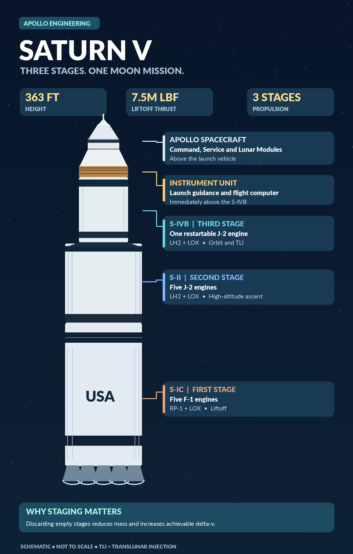
The solution was a three-stage rocket in which each stage operated at a different phase of flight. The S-IC first stage supplied the enormous thrust needed for liftoff. The S-II second stage provided sustained acceleration using high-efficiency hydrogen engines. The S-IVB third stage completed orbital insertion and later restarted to perform translunar injection, the maneuver that sent the Apollo spacecraft toward the Moon.
Understanding how Saturn V worked requires examining not only its engines but also the physics of rocket staging, the control systems that guided its trajectory, and the Apollo spacecraft it carried.

Saturn V Rocket Specifications at a Glance
| Characteristic | Saturn V specification |
|---|---|
| Developer | NASA and major aerospace contractors |
| Primary mission | Apollo crewed lunar missions |
| Height | Approximately 363 ft (111 m) |
| Maximum main-body diameter | 33 ft (10.1 m) |
| Liftoff mass | Approximately 6.2 million lb (2.8 million kg) |
| First-stage liftoff thrust | Approximately 7.5 million lbf (33.4 MN) |
| Propulsion stages | Three |
| First-stage engines | Five Rocketdyne F-1 |
| Second-stage engines | Five Rocketdyne J-2 |
| Third-stage engine | One restartable Rocketdyne J-2 |
| First-stage propellants | RP-1 kerosene and liquid oxygen |
| Upper-stage propellants | Liquid hydrogen and liquid oxygen |
| First launch | November 9, 1967 |
| Final launch | May 14, 1973 |
| Total launches | 13 |
| Crewed lunar landing missions supported | Six |
Sources: NASA Saturn V historical records, NASA educational material, and Smithsonian National Air and Space Museum. Figures are representative, not specifications for every individual Saturn V flight. [1][2][3]
Understanding the Saturn V Rocket’s Design and Architecture
Why NASA Developed the Saturn V
NASA developed Saturn V to meet the extraordinary requirements of the Apollo program, particularly the national objective announced by President John F. Kennedy in 1961: landing astronauts on the Moon and returning them safely to Earth before the decade ended.
Sending people to the Moon demanded far more propulsion capability than launching a small satellite or placing a spacecraft in low Earth orbit. The vehicle had to accelerate a complete lunar spacecraft assembly, carrying astronauts, life-support systems, landing equipment, electrical systems, propulsion hardware, and substantial quantities of propellant.
NASA also had to account for the energy required to escape low Earth orbit and travel toward the Moon. Simply reaching an altitude commonly described as space would not be enough.
A crucial design decision was the adoption of lunar orbit rendezvous, in which a specialized Lunar Module would descend to the Moon while the Command and Service Module remained in lunar orbit. This strategy reduced the mass that had to land on the surface and subsequently return to lunar orbit.
Development was coordinated by NASA’s Marshall Space Flight Center, with major contributions from Boeing, North American Aviation, Douglas Aircraft, Rocketdyne, and IBM. Each organization specialized in different stages, propulsion systems, structures, or computing technologies. [2][18]
How the Three-Stage Rocket Architecture Worked
A three-stage rocket consists of three major propulsion sections that operate sequentially. When one stage finishes its work, it separates from the remainder of the vehicle, allowing the next stage to accelerate a much lighter spacecraft.
Saturn V was designed around three distinct propulsion systems.
| Stage | Main purpose | Engines | Propellants |
|---|---|---|---|
| S-IC | Liftoff and early ascent | Five F-1 | RP-1 and LOX |
| S-II | High-altitude acceleration | Five J-2 | LH2 and LOX |
| S-IVB | Earth orbit insertion and translunar injection | One J-2 | LH2 and LOX |
The first stage was optimized for tremendous thrust near sea level. The second stage operated after much of the atmosphere had been left behind, where propulsion efficiency became increasingly important. The third stage performed two separate burns, making it essential for transforming an Earth-orbit mission into a lunar mission.
This architecture allowed NASA to select engines, propellants, and structural arrangements suited to each flight phase rather than requiring one propulsion system to meet every condition. [2][6]
Rocket Staging: Why Saturn V Discarded Its Empty Stages
Rocket staging is the process of discarding sections of a launch vehicle after they have consumed their usable propellant and completed their propulsion tasks.
An empty rocket stage still has considerable mass. Its engines, tanks, piping, structural supports, and protective equipment would become unnecessary weight if carried throughout the remainder of the mission.
By separating its depleted stages, Saturn V reduced the mass that the remaining engines needed to accelerate. This improved the vehicle’s achievable velocity change, known as delta-v.
Stage separation required carefully coordinated mechanical and propulsion operations. Interstage structures connected the stages and carried mechanical loads during powered flight. Separation systems released these connections at the appropriate time.
Small solid-propellant retrorockets helped move spent stages away from the continuing vehicle. Ullage motors or other acceleration-producing systems helped ensure suitable propellant conditions before upper-stage engine ignition.
These operations had to occur in the correct sequence because an engine starting too early, a stage failing to separate, or inadequate clearance could jeopardize the mission. [18]
The S-IC First Stage: How Saturn V Lifted Off Earth
Understanding the S-IC First Stage
The S-IC was Saturn V’s massive first-stage booster and the primary source of propulsion during the initial portion of launch. It stood approximately 138 feet (42 meters) tall and had a main diameter of 33 feet (10.1 meters).
Its structure contained large tanks for liquid oxygen and RP-1 kerosene, along with five powerful F-1 rocket engines arranged in a cluster at its base.
The center engine was fixed, while the four surrounding engines could pivot to control the rocket’s direction.
The first stage had the most demanding initial propulsion requirement because it had to lift the complete Saturn V spacecraft stack while working against gravity and atmospheric drag.
As the engines consumed propellant, the vehicle became progressively lighter. This allowed its acceleration to increase as the flight continued.
The S-IC operated for roughly the first two and a half minutes of a typical lunar mission before shutting down and separating from the upper stages. [3][18]
Inside the F-1 Rocket Engine
The F-1 rocket engine was a giant liquid-propellant engine developed by Rocketdyne. Each F-1 produced approximately 1.5 million pounds-force of thrust at sea level, giving Saturn V’s five-engine first stage a combined nominal liftoff thrust of approximately 7.5 million pounds-force.
The F-1 operated by pumping large quantities of kerosene and liquid oxygen into a combustion chamber. The propellants reacted, generating extremely hot, high-pressure gases that expanded through a rocket nozzle.
The engine combined several sophisticated subsystems, including high-capacity turbopumps, propellant injectors, a regeneratively cooled thrust chamber, and exhaust management equipment.
According to the Smithsonian Institution, the F-1 turbopump delivered propellants at approximately 42,500 gallons per minute. That immense flow rate reflects the extraordinary quantity of propellant needed to sustain its thrust.
One of the most difficult development challenges was combustion instability, which could create destructive pressure oscillations inside the enormous chamber. NASA and Rocketdyne addressed the problem through extensive testing and improvements to the injector system. [3][10]
RP-1 Rocket Kerosene and Liquid Oxygen
The S-IC burned RP-1, a highly refined petroleum-based rocket fuel, together with liquid oxygen, commonly abbreviated LOX.
RP-1 was suitable for the first stage because kerosene has relatively high density, allowing large quantities of fuel to be stored without excessively large tanks. It also provided practical handling and storage advantages compared with liquid hydrogen.
Liquid oxygen acted as the oxidizer. It supplied the oxygen required for combustion, allowing the engines to operate independently of the surrounding atmosphere.
This is a fundamental difference between rocket propulsion and conventional air-breathing jet engines. A rocket carries both fuel and oxidizer, so it can continue producing thrust in space, where there is virtually no atmospheric oxygen.
The RP-1 and LOX combination provided the high thrust required during early ascent. Saturn V’s upper stages used liquid hydrogen instead because its higher specific impulse offered significant advantages once the rocket was moving toward orbital conditions.
How Rocket Thrust Lifted the Saturn V
Rocket thrust can be understood through Newton’s laws of motion and the conservation of momentum.
Inside an F-1 engine, combustion produces hot gases that are accelerated through an exhaust nozzle at very high velocity. As the rocket expels momentum in one direction, it experiences a corresponding force in the opposite direction.
For liftoff to occur, the combined upward thrust must exceed the downward gravitational force acting on the launch vehicle.
The initial thrust-to-weight ratio can be expressed as:
Here, Fthrust is the engine thrust, m is the rocket’s instantaneous mass, and g is gravitational acceleration.
Using the commonly cited approximate figures of 7.5 million pounds-force of thrust and 6.2 million pounds of liftoff weight gives an initial thrust-to-weight ratio of about 1.21.
This means Saturn V initially accelerated upward relatively slowly. As it burned propellant and its mass decreased, its thrust-to-weight ratio increased, allowing greater acceleration. [1][8]
Engine Ignition Sequence and Liftoff
Saturn V did not release itself from the launch pad the instant its engines received ignition commands.
Instead, its five F-1 engines followed a controlled startup sequence. The center engine started first, followed by the four outer engines in opposing pairs. This arrangement helped maintain a controlled thrust buildup while the rocket remained secured.
The launch pad’s hold-down mechanisms restrained the rocket while ground systems verified engine operation. Only after the engines achieved acceptable thrust and operating conditions could the launch sequence proceed to release.
This approach reduced the risk of releasing an enormous launch vehicle with insufficient or abnormal thrust.
After release, Saturn V rose from Launch Complex 39A and began following its programmed ascent trajectory. Guidance commands gradually changed the rocket’s attitude, allowing it to build the horizontal velocity necessary for reaching orbit.
First-Stage Engine Cutoff and Separation
The S-IC’s main engines shut down near the end of the first stage’s planned propulsion phase.
For a typical Apollo lunar ascent, the center F-1 engine shut down before the four outer engines. This helped manage the increasing acceleration experienced by the vehicle as propellant was consumed.
When the remaining engines completed their burn, the first stage was ready for separation.
The stage connection was released, and retrorockets helped move the spent booster away from the continuing vehicle. The upper stages were then able to proceed with second-stage propulsion.
The discarded S-IC subsequently followed a ballistic trajectory toward the Atlantic Ocean. It was not designed for controlled landing and reuse.
This separation substantially reduced the mass carried by the upper stages, making the next phase of acceleration much more efficient. [5][18]
The S-II Second Stage: Accelerating Toward Space
Understanding the S-II Second Stage
The S-II was Saturn V’s second propulsion stage, responsible for accelerating the spacecraft after separation from the first-stage booster.
Approximately 82 feet (25 meters) long and 33 feet (10.1 meters) in diameter, it was powered by five J-2 engines arranged with one central engine and four surrounding engines.
Unlike the first stage, the S-II used liquid hydrogen as fuel and liquid oxygen as oxidizer.
Its operation began at high altitude, after the S-IC had already carried the vehicle through the densest portion of the atmosphere. As a result, the S-II could take advantage of engines optimized for the increasingly low-pressure environment.
The second stage provided much of the remaining acceleration needed to approach orbital velocity. Its performance was especially important because the spacecraft still carried the S-IVB, the Apollo spacecraft, and the propellant required for lunar departure. [2][18]
How the J-2 Rocket Engine Worked
The J-2 rocket engine was a liquid-hydrogen and liquid-oxygen rocket engine developed by Rocketdyne for Saturn upper-stage propulsion.
Five J-2 engines powered the S-II, producing a combined nominal vacuum thrust of approximately 1.15 million pounds-force, depending on the specific engine configuration and operating conditions.
Like the F-1, the J-2 used turbopumps to deliver fuel and oxidizer into a combustion chamber. However, hydrogen-based propulsion provided greater specific impulse than kerosene-based propulsion.
This meant the J-2 could produce more total impulse per unit weight of propellant, an important advantage when the vehicle needed additional velocity rather than maximum initial liftoff thrust.
The J-2 was also central to Saturn V’s lunar capability because the version used on the S-IVB could restart after an orbital coast period, making a second major propulsion maneuver possible.
Liquid Hydrogen (LH2) as an Upper-Stage Fuel
Liquid hydrogen, abbreviated LH2, is hydrogen cooled to an extremely low temperature so that it remains liquid.
When burned with liquid oxygen in a rocket engine, hydrogen can provide high specific impulse because the resulting exhaust has favorable thermodynamic and molecular properties.
However, hydrogen has a major drawback: very low density.
A tank holding a given mass of liquid hydrogen must be much larger than a tank containing the same mass of a denser fuel such as RP-1. That increases structural and insulation demands.
Hydrogen also requires complicated cryogenic storage, careful thermal management, and procedures to minimize propellant losses.
For Saturn V, these disadvantages were acceptable in the upper stages because their propulsion efficiency directly influenced how much useful mass could reach Earth orbit and travel toward the Moon.
The first stage prioritized compact storage and very high thrust. The second and third stages prioritized higher exhaust performance.
Cryogenic Propellant Storage and Insulation
Both liquid hydrogen and liquid oxygen are cryogenic propellants, meaning they must be maintained at temperatures far below ordinary environmental conditions.
Liquid hydrogen is typically stored near minus 423°F (minus 253°C), while liquid oxygen is stored near minus 297°F (minus 183°C). These temperatures require insulated tanks, specialized piping, careful material selection, and thermal conditioning procedures. [7]
The S-II and S-IVB incorporated a common bulkhead, a structural arrangement in which adjacent propellant tanks shared a separating structure rather than using two completely independent tank ends.
This reduced structural mass and helped make the stages more efficient. However, the bulkhead also had to accommodate the large temperature difference between liquid oxygen and liquid hydrogen.
Thermal insulation was necessary to limit heat transfer, excessive evaporation, and unwanted changes in propellant conditions.
Cryogenic systems also had to tolerate structural contraction, thermal stresses, and changes in the vehicle’s flight environment.
These requirements made Saturn V’s hydrogen stages considerably more complicated than ordinary fuel-storage tanks.
S-II Engine Shutdown and Stage Separation
After several minutes of operation, the S-II approached the conditions required for third-stage flight.
Its engines shut down when the planned propulsion objectives were reached. At this point, the vehicle was traveling at high speed and was already at substantial altitude, but the complete Earth parking orbit had not yet been established.
The S-II separated from the S-IVB through a precisely sequenced operation involving engine shutdown, structural separation, clearance, and third-stage ignition preparation.
The S-IVB then assumed responsibility for the remaining orbital insertion maneuver.
The timing of these events was critical. A delayed shutdown, separation failure, or unsuccessful third-stage ignition could prevent the spacecraft from reaching its intended orbit.
After separation, the S-II became a discarded launch-vehicle component, while the third stage continued carrying the Apollo spacecraft toward its initial orbital destination.
The S-IVB Third Stage: From Earth Orbit to the Moon
Understanding the S-IVB Third Stage
The S-IVB was the final propulsion stage of Saturn V and one of the most important components of the entire lunar mission architecture.
Approximately 59 feet (18 meters) long and 21.7 feet (6.6 meters) in diameter, it carried a single J-2 engine powered by liquid hydrogen and liquid oxygen.
Unlike the earlier stages, the S-IVB was designed to perform two major powered maneuvers separated by an extended period of unpowered flight.
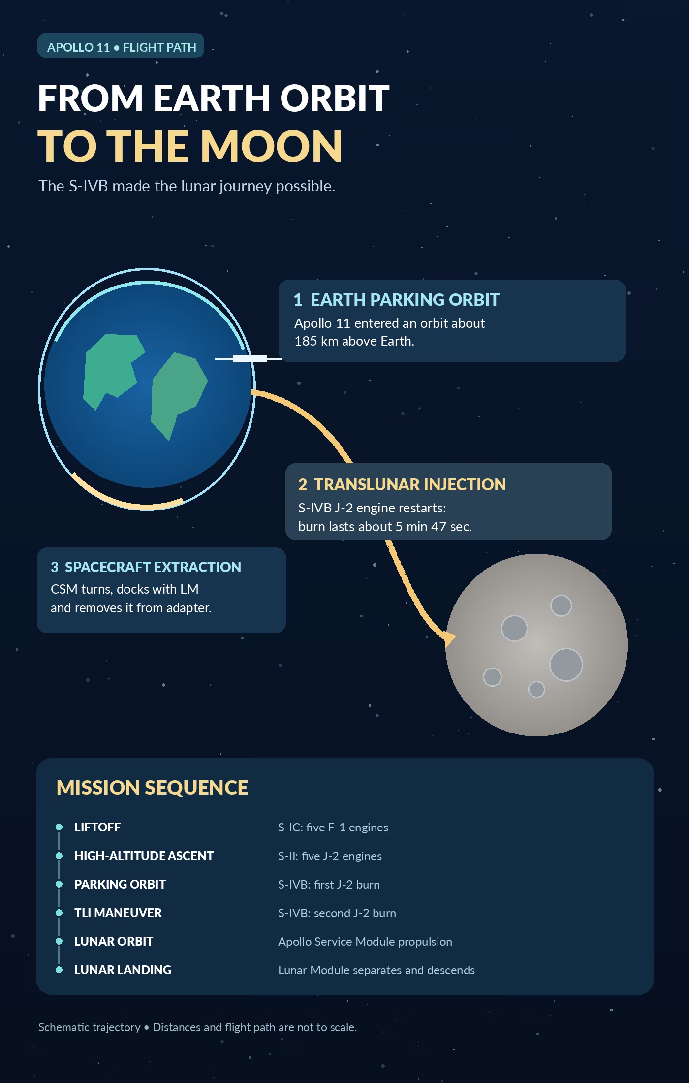
Its first burn completed the ascent into low Earth orbit. After the spacecraft had coasted in orbit and passed mission-readiness checks, the stage restarted its J-2 engine to accelerate Apollo toward the Moon.
This second burn, known as translunar injection, made the S-IVB more than an ordinary orbital upper stage. It was the propulsion system that enabled Apollo to leave Earth parking orbit on its planned lunar-transfer trajectory. [6]
Orbital Insertion: Reaching Earth Orbit
Reaching space and achieving Earth orbit are not the same thing.
A spacecraft can rise above the atmosphere and still fall back to Earth if it lacks sufficient horizontal velocity. Remaining in orbit requires moving sideways fast enough that Earth’s curvature effectively falls away beneath the spacecraft as gravity continuously bends its path.
The S-IVB supplied the final powered acceleration needed to place the Apollo spacecraft into its intended parking orbit.
For Apollo 11, NASA’s postflight records indicate an initial orbit of approximately 100.4 by 98.9 nautical miles, equivalent to roughly 186 by 183 kilometers, with an orbital inclination of about 32.5 degrees. [5]
The launch vehicle’s guidance system calculated and controlled the required propulsion conditions, terminating the first S-IVB burn when the appropriate orbital parameters had been achieved.
At this point, Apollo was orbiting Earth, but its journey to the Moon had not yet begun.
Earth Parking Orbit and Mission Preparation
An Earth parking orbit is a temporary orbit used before a spacecraft performs another major propulsion maneuver.
Apollo missions used this phase to verify that the spacecraft and launch vehicle were functioning properly before committing to lunar departure.
Astronauts and ground controllers monitored important systems, including navigation, communications, electrical power, propulsion conditions, and spacecraft status.
The S-IVB remained physically connected to the Apollo spacecraft during this coast period. Its J-2 engine was shut down, and the combined vehicle traveled around Earth without continuous main-engine thrust.
The parking orbit also provided the appropriate geometric conditions for performing the translunar injection maneuver at the planned time.
For Apollo 11, the S-IVB restarted after approximately two hours and 44 minutes of mission elapsed time, during the spacecraft’s second revolution around Earth. [4]
Ullage Rockets and Propellant Settling
In microgravity, liquid propellants do not automatically remain pooled at the bottom of their tanks.
Instead, they can move, float, form droplets, or collect in locations determined by surface tension, residual acceleration, tank geometry, and fluid motion.
This creates a problem for rocket engines because turbopumps must receive properly conditioned liquid propellant rather than an unpredictable mixture of liquid and gas.
Ullage refers to the gas or unfilled volume within a tank. In rocket operations, an ullage maneuver uses a small acceleration to help settle propellants toward tank outlets.
The S-IVB used auxiliary propulsion systems and carefully designed fluid-management measures to control propellant behavior during orbital coasting and before restart.
NASA’s research into hydrogen slosh, tank baffles, and propellant settling was essential to making the third-stage restart practical. [6]
S-IVB Engine Restart
Restarting the J-2 after orbital coasting was an important technical achievement because the engine had to operate reliably after its first shutdown.
Before the second ignition, the vehicle had to achieve the correct attitude, settle its remaining propellants, maintain appropriate tank pressure, and condition the engine’s feed systems.
Hydrogen and oxygen delivery had to be controlled so the engine could establish stable combustion rather than experiencing unacceptable flow or ignition conditions.
The restart sequence was managed through the launch vehicle’s onboard control systems, with ground controllers monitoring telemetry and mission readiness.
This capability was essential because the Apollo spacecraft could not rely on its own propulsion system to replace the entire planned translunar injection performance of the S-IVB.
NASA’s engineering investigations into cryogenic fluid behavior and engine restart contributed directly to the success of the Apollo lunar missions.
Translunar Injection: Leaving Earth Orbit
Translunar injection, usually abbreviated TLI, is the propulsion maneuver that changes a spacecraft’s trajectory from Earth orbit to a path that approaches the Moon.
During TLI, the S-IVB J-2 engine reignited and accelerated the combined Apollo spacecraft and upper stage in a carefully calculated direction.
For Apollo 11, the second burn lasted approximately 347 seconds, or about five minutes and 47 seconds. NASA’s mission records place ignition at approximately 2 hours, 44 minutes, and 16 seconds after liftoff. [4][5]
The maneuver increased Apollo’s orbital energy substantially. Rather than remaining in its low-altitude circular parking orbit, the spacecraft entered a lunar-transfer trajectory.
The exact timing, direction, and duration of the burn influenced the spacecraft’s arrival conditions near the Moon.
Following TLI, the Command and Service Module separated, turned around, docked with the Lunar Module, and extracted it from the adapter attached to the S-IVB.
The spent S-IVB was subsequently separated from the Apollo spacecraft. Its final trajectory and disposal depended on the specific mission, with some upper stages directed toward solar orbits and others toward lunar impacts.
How the Saturn V Rocket Engines Generated Power
Inside a Liquid-Fueled Rocket Engine
Saturn V’s F-1 and J-2 engines used the same fundamental propulsion principle: chemical energy from the reaction between fuel and oxidizer was converted into high-speed exhaust and mechanical thrust.
Both were liquid-propellant rocket engines, but they differed in propellant selection, chamber design, operating conditions, and performance objectives.
The main propulsion process involved several interconnected operations:
- Propellants were stored in separate fuel and oxidizer tanks.
- Feed systems delivered the liquids to the engines.
- Turbopumps raised the propellant pressure.
- Injectors distributed fuel and oxidizer into the combustion chamber.
- Combustion produced high-temperature, high-pressure gases.
- The exhaust nozzle accelerated those gases to generate thrust.
The major advantage of this arrangement was that engine output could be controlled through precisely engineered propellant flow, combustion, and shutdown systems.
The F-1 and J-2 both used gas-generator-cycle propulsion, although their detailed designs differed. A portion of the propellant energy powered turbines connected to the main pumps, while the main combustion chamber produced most of the useful thrust. [17]
Rocket Turbopump: Moving Propellants at High Pressure
A rocket turbopump is a high-speed pumping system that delivers fuel and oxidizer to a combustion chamber at pressures and flow rates far beyond those of ordinary industrial pumping equipment.
Large rocket engines cannot achieve their required thrust simply by allowing propellants to flow under gravity. The liquids must enter the combustion chamber at sufficient pressure to support controlled injection and combustion.
In Saturn V’s engines, turbines provided mechanical energy to drive the pumps. The pumps then forced liquid propellants through the engine’s feed system.
The F-1 turbopump was particularly demanding because the engine consumed an enormous amount of propellant during each second of operation.
Engineers had to solve problems involving pump cavitation, pressure fluctuations, rotating machinery, sealing, and the behavior of cryogenic liquid oxygen.
These pumps were not secondary accessories. Without reliable high-pressure propellant delivery, neither the enormous thrust of the F-1 nor the efficient operation of the J-2 would have been possible. [3][17]
Propellant Injector: Mixing Fuel and Oxidizer
A propellant injector distributes fuel and oxidizer into a rocket engine’s combustion chamber in carefully controlled patterns.
Effective injection must create suitable mixing and combustion conditions while preventing destructive pressure fluctuations.
In liquid-propellant engines, injector design influences combustion efficiency, chamber temperature distribution, ignition behavior, and stability.
The F-1 presented an especially difficult challenge because its enormous combustion chamber could support damaging high-frequency pressure oscillations.
Early development testing revealed that uncontrolled combustion instability could threaten the engine itself.
Engineers eventually incorporated baffles into the injector face, dividing the combustion region into sections that helped suppress damaging oscillations.
NASA and Rocketdyne validated these changes through extensive hot-fire testing, including tests that deliberately introduced disturbances to determine whether the engine would recover stable combustion.
The resulting injector system became one of the most important engineering solutions in the F-1 development program. [10]
Combustion Chamber: Producing High-Energy Gases
The combustion chamber is the part of a rocket engine in which fuel and oxidizer chemically react and release energy.
The reaction creates hot gases at high pressure. These gases are then directed through a nozzle, where their thermal and pressure energy is converted into high exhaust velocity.
The chamber must survive extremely demanding conditions, including intense heat transfer, pressure loading, vibration, and repeated thermal changes.
Saturn V’s liquid-fueled engines relied on sophisticated cooling techniques. Regenerative cooling circulated fuel through passages around portions of the chamber and nozzle, absorbing heat before the fuel entered the combustion process.
This helped protect engine structures against temperatures that would otherwise exceed the capabilities of their materials.
The combustion chamber also had to maintain stable pressure during engine operation. Instability could damage internal components or produce unacceptable fluctuations in thrust.
Consequently, chamber construction, cooling, injectors, and propellant delivery had to function as one integrated system.
Rocket Exhaust Nozzle: Converting Energy Into Thrust
A rocket nozzle transforms the energy of high-pressure combustion gases into a high-velocity exhaust stream.
Saturn V used converging-diverging nozzles. Gas passed through a narrowing region called the throat and then expanded through the nozzle’s diverging section.
For the appropriate pressure conditions, this geometry accelerates the exhaust to supersonic velocity.
The resulting momentum flow produces thrust. A more complete expression for rocket thrust is:
Where:
- F is thrust.
- ṁ is exhaust mass-flow rate.
- ve is exhaust velocity.
- pe is nozzle exit pressure.
- pa is ambient pressure.
- Ae is nozzle exit area.
The equation demonstrates why ambient pressure affects rocket-engine performance.
At sea level, atmospheric pressure influences nozzle expansion and effective thrust. At high altitude, reduced ambient pressure generally allows greater effective thrust for a given engine configuration.
This is one reason upper-stage engines can use nozzle designs that are better suited to operation in near-vacuum conditions.
Specific Impulse and Rocket Efficiency
Specific impulse, written as Isp, is a standard measure of how efficiently a rocket engine uses propellant.
It describes the total impulse produced per unit weight of propellant consumed and is commonly expressed in seconds.
For a simplified steady-flow rocket engine:
Here, F is thrust, ṁ is propellant mass-flow rate, and g0 is standard gravitational acceleration.
Higher specific impulse means an engine can achieve a greater velocity change from a given propellant mass under otherwise comparable conditions.
Historical Saturn V engine specifications show approximately 260 to 263 seconds of minimum sea-level specific impulse for F-1 configurations and approximately 418 to 421 seconds for J-2 configurations at altitude. Exact figures depend on engine version and operating conditions. [21]
The distinction explains a fundamental Saturn V design decision: maximum thrust and maximum propellant efficiency were not the same objective.
The F-1 delivered enormous liftoff thrust, while the hydrogen-fueled J-2 provided the higher specific impulse valuable for reaching orbit and traveling toward the Moon.
The Physics That Made Saturn V’s Moon Mission Possible
Delta-V: How Rockets Change Velocity
Delta-v, represented by the symbol Δv, describes the change in velocity that a propulsion system can provide.
For space missions, delta-v is one of the most important quantities in trajectory planning because different maneuvers require different changes in spacecraft velocity.
Saturn V’s mission involved several major propulsion requirements: lifting through the atmosphere, accelerating toward orbital velocity, completing orbital insertion, and performing translunar injection.
It is important to distinguish total ideal delta-v capability from the final speed of a spacecraft. During ascent, some propulsion capability is consumed in overcoming gravity and atmospheric drag. Therefore, a launch vehicle generally requires more ideal delta-v than the final orbital speed alone would suggest.
NASA’s engineers allocated propulsion capability among the three stages based on their mass, engine performance, and flight responsibilities.
The S-IC supplied the initial acceleration, the S-II contributed efficient high-altitude propulsion, and the S-IVB completed the orbital and lunar-departure maneuvers. [8]
Propellant Mass Fraction and the Rocket Equation
A rocket’s performance depends heavily on how much of its initial mass consists of usable propellant.
The propellant mass fraction can be expressed as:
Here, mp is propellant mass and m0 is the initial mass of the rocket or stage under consideration.
A high propellant mass fraction is desirable because a rocket must accelerate its structure, engines, tanks, and payload along with the remaining fuel.
The relationship between propellant consumption and ideal velocity change is described by the Tsiolkovsky rocket equation:
Where mf is the final mass after the propellant has been consumed.
This equation shows that achievable ideal velocity change depends on both specific impulse and mass ratio.
Saturn V improved its performance through high-energy propellants, lightweight structural design, and staging.
Common bulkheads helped reduce tank mass, while stage separation removed structures and engines that were no longer needed.
The equation describes ideal rocket behavior. Actual ascent calculations must also account for gravity, aerodynamic drag, steering, and other trajectory effects. [8]
Payload Capacity: How Much Could Saturn V Carry?
Payload capacity describes the mass that a rocket can deliver to a specified orbit or trajectory.
A rocket does not have one universal payload capacity. The amount it can deliver depends on the mission destination, orbital altitude, inclination, and required velocity change.
NASA’s historical technical records list a Saturn V capability of approximately 129 metric tons to a 195-kilometer Earth orbit, together with roughly 45 metric tons to an escape trajectory in the cited configuration. Other mission documents give different rounded figures for particular payload and trajectory assumptions. [2]
Saturn V’s extraordinary lifting capability was necessary because Apollo carried more than a crew capsule.
The complete lunar mission assembly included the Command Module, Service Module, Lunar Module, propellants, equipment, and supporting structures.
After Earth orbit was achieved, the S-IVB needed to accelerate this substantial spacecraft assembly toward the Moon.
This explains why a launcher capable of placing a heavy payload into low Earth orbit was not automatically capable of sending the same mass on a lunar mission.
The greater the destination energy requirement, the more demanding the payload and propellant trade-offs become.
How Saturn V Navigated and Controlled Its Flight
The Instrument Unit: Saturn V’s Electronic Brain
The Saturn V Instrument Unit, often abbreviated IU, was a ring-shaped section installed above the S-IVB third stage and below the Apollo spacecraft.
It housed much of the launch vehicle’s guidance, navigation, control, computing, electrical, and flight-sequencing equipment.
IBM manufactured the Instrument Unit for NASA’s Marshall Space Flight Center. Its structure supported critical electronics while also forming part of the mechanical connection between the third stage and the spacecraft.
The IU included a digital computer, inertial reference equipment, control electronics, batteries, and supporting systems.
Its location allowed it to manage the Saturn V during first-stage ascent, second-stage acceleration, orbital insertion, and third-stage operations.
The Instrument Unit was separate from the Apollo spacecraft’s own guidance systems. This distinction matters because Saturn V’s launch guidance computer did not perform the entire lunar landing mission.
After launch-vehicle operations ended, guidance responsibilities shifted to the Apollo spacecraft’s systems and mission-control procedures. [9][22]
Guidance, Navigation and Control (GNC)
Guidance, navigation, and control are three closely related but technically distinct functions.
Guidance determines the desired trajectory and calculates how the vehicle should move to meet mission objectives.
Navigation estimates the spacecraft’s current position, velocity, and orientation using measurements from onboard instruments and other available information.
Control produces physical actions to make the vehicle follow the required trajectory, such as changing the direction of engine thrust.
These functions operate together.
If navigation measurements show that the rocket is deviating from its planned path, guidance calculations determine the required correction. Control systems then command engine steering or other appropriate actuators.
For Saturn V, accurate trajectory management was essential because small errors in velocity or direction could create significant changes in the spacecraft’s eventual position.
The system had to respond to changing acceleration, vehicle mass, structural dynamics, and flight conditions while maintaining a trajectory compatible with orbital insertion and translunar injection.
Launch Vehicle Digital Computer
The Launch Vehicle Digital Computer, or LVDC, was the primary onboard computer used for Saturn V launch-vehicle guidance calculations.
Developed by IBM, it processed information from the vehicle’s inertial navigation equipment and other systems to calculate steering and sequencing commands.
The LVDC worked with the Launch Vehicle Data Adapter, which helped interface the computer with measurement, control, and other vehicle systems.
Its responsibilities included managing portions of the ascent guidance program, supporting orbital insertion, and controlling the S-IVB’s restart and translunar injection sequence.
The LVDC also used reliability-oriented design techniques, including redundant circuitry, to reduce the likelihood that an individual electronic failure would cause loss of guidance.
An onboard computer was essential because Saturn V required immediate calculations and control responses throughout its flight.
Ground controllers monitored performance and could provide certain updates, but the vehicle could not depend on continuous manual steering from Earth. [9][22]
Inertial Guidance Platform
Saturn V used an inertial guidance system based on the ST-124 stabilized platform.
An inertial reference platform uses gyroscopes and accelerometers to measure orientation and motion relative to an established reference frame.
Gyroscopes help maintain or determine the platform’s orientation, while accelerometers measure specific force. These measurements can be processed to estimate changes in velocity and spacecraft motion.
The ST-124 system supplied critical navigation measurements to the launch vehicle’s computer and related electronics.
Unlike systems that depend entirely on external radio signals, inertial navigation can operate autonomously after initial alignment.
However, inertial navigation is not perfectly error-free. Sensor inaccuracies and integration errors can accumulate over time.
For Saturn V, the platform provided sufficiently accurate real-time information to support ascent steering and upper-stage propulsion.
NASA complemented onboard guidance with ground-based tracking, mission analysis, and updates when necessary. [9]
Gimbaled Rocket Engines and Thrust Vector Control
Saturn V controlled much of its powered flight by changing the direction of engine thrust.
This technique is called thrust vector control, or TVC.
A gimbaled engine can pivot around one or more axes, allowing its thrust vector to tilt relative to the rocket’s centerline.
When thrust no longer acts directly through the vehicle’s center of mass, it creates a turning moment that can change the rocket’s attitude.
Saturn V used gimbaled engines on all three propulsion stages.
On the S-IC and S-II, the four outer engines provided major steering capability, while the central engine was fixed. The S-IVB used its single gimbaled J-2 engine for powered-flight steering.
Guidance commands were converted into engine movements by control electronics and hydraulic actuators.
These movements enabled the rocket to control pitch and yaw, while roll control depended on the specific stage’s engine arrangement and auxiliary control capabilities.
Thrust vector control eliminated the need for large aerodynamic steering surfaces and remained effective where atmospheric air was too thin for conventional fins to work.
Gravity Turn Maneuver: Steering Toward Orbit
A gravity turn is a launch-vehicle ascent technique in which a rocket gradually transitions from a nearly vertical trajectory toward a predominantly horizontal flight path.
This maneuver is necessary because achieving orbit depends primarily on gaining sufficient horizontal velocity, not simply reaching a great altitude.
Saturn V began its ascent almost vertically to clear the launch infrastructure. It then performed programmed roll and pitch maneuvers that established the required flight direction.
After this initial steering, the rocket continued following an optimized ascent trajectory in which gravity and engine guidance helped shape its flight path.
Engineers had to balance several competing requirements.
Climbing too vertically for too long would increase gravity losses. Turning too aggressively in dense atmosphere could create unacceptable aerodynamic loads.
The trajectory therefore had to account for aerodynamic pressure, structural bending, engine performance, and the desired final orbit.
For Apollo 11, NASA’s flight timeline records the beginning of the pitch and roll maneuver approximately 13 seconds after liftoff. [5]
The Apollo Spacecraft Carried by Saturn V
Command and Service Module (CSM)
The Apollo Command and Service Module, or CSM, formed the primary spacecraft used by astronauts during much of their journey between Earth and the Moon.
It consisted of two connected spacecraft sections with different responsibilities.
The Command Module contained the pressurized crew cabin, flight controls, navigation equipment, communications systems, and the heat shield needed for atmospheric reentry.
The Service Module supplied major supporting functions, including propulsion, electrical power, oxygen, and other consumables.
Its Service Propulsion System provided the large maneuvers needed for lunar orbit insertion and the return journey from the Moon.
During Apollo 11, the Command Module was named Columbia.
After the Saturn V completed translunar injection, the CSM performed the transposition and docking maneuver required to retrieve the Lunar Module.
Near the end of the mission, the Service Module separated from the Command Module before atmospheric entry.
Only the Command Module returned the astronauts to Earth’s surface. [12]
Lunar Module (LM): The Spacecraft That Landed on the Moon
The Apollo Lunar Module was a specialized spacecraft designed to operate in the vacuum and low-gravity environment of the Moon.
It did not need to survive atmospheric reentry or operate as an aerodynamic vehicle.
The LM was divided into two major sections.
The descent stage contained the main landing engine, landing gear, and equipment required to approach and land on the lunar surface.
The ascent stage contained the crew cabin, controls, and propulsion system required to lift off from the Moon and return astronauts to lunar orbit.
During Apollo 11, the Lunar Module was named Eagle.
Neil Armstrong and Buzz Aldrin descended to the lunar surface aboard Eagle, while Michael Collins remained in Columbia in lunar orbit.
After surface operations were completed, Eagle’s ascent stage launched from the Moon, leaving its descent stage behind.
This division of responsibilities minimized the mass that had to return to lunar orbit. [12][19]
Spacecraft-Lunar Module Adapter (SLA)
The Spacecraft-Lunar Module Adapter, abbreviated SLA, was the structural enclosure that connected the Apollo Command and Service Module to the Saturn V’s upper launch-vehicle assembly.
The adapter surrounded and protected the Lunar Module during launch.
Its external shape provided an appropriate aerodynamic transition between the narrower Apollo spacecraft and the rocket structure below.
The SLA also transferred structural loads through the combined spacecraft and launch vehicle during ascent.
Once Saturn V completed translunar injection, the adapter no longer needed to enclose the Lunar Module.
Its panels were released so the CSM could separate, turn around, and dock with the exposed LM.
The adapter therefore served two different engineering purposes: protecting the lunar lander during the demanding launch environment and allowing its extraction during the mission’s spacecraft-reconfiguration phase.
Transposition, Docking and Extraction
Transposition, docking, and extraction was the procedure used to connect the Apollo Command and Service Module with the Lunar Module after the translunar injection maneuver.
During launch, the CSM was positioned above the spacecraft-lunar module adapter, while the LM was enclosed inside the adapter.
After the S-IVB completed its second burn, the CSM separated from the launch-vehicle assembly.
The Command Module Pilot then maneuvered the spacecraft away, rotated it approximately 180 degrees, and aligned it with the Lunar Module.
The CSM approached the LM and completed docking.
After the spacecraft were securely connected, the Lunar Module was released from the adapter and extracted.
The combined CSM and LM could then continue toward the Moon.
This maneuver was essential because the Lunar Module needed to be securely attached to the Command Module for crew transfer and later lunar-orbit operations.
Lunar Orbit Rendezvous (LOR)
Lunar orbit rendezvous was the mission architecture NASA selected for the Apollo lunar landings.
Rather than landing the complete Apollo spacecraft on the Moon, NASA used a smaller Lunar Module dedicated to the descent and return to lunar orbit.
The Command and Service Module remained in lunar orbit while the LM descended.
Once surface operations were complete, the LM ascent stage returned to orbit and performed a rendezvous and docking maneuver with the CSM.
The astronauts and collected lunar samples transferred back into the Command Module before the LM ascent stage was discarded.
This approach dramatically reduced the mass that had to land on the Moon and subsequently lift off.
It also reduced the total propulsion requirements compared with landing and launching a large Earth-return spacecraft from the lunar surface.
NASA formally selected lunar orbit rendezvous in July 1962. The decision was central to making the Apollo lunar landing mission compatible with Saturn V’s payload capacity and development schedule. [19]
Safety Systems and Engineering Challenges
Launch Escape System: Protecting Apollo Astronauts
The Apollo Launch Escape System, or LES, was an emergency propulsion system mounted above the Command Module during launch.
Its primary purpose was to pull the crew capsule away from the launch vehicle if a serious emergency occurred during the early phases of flight.
The system included solid-propellant rocket motors and supporting equipment designed to separate the Command Module from a malfunctioning rocket and move it toward a safer trajectory.
The escape system was particularly important while the Saturn V was on the launch pad and during the lower-altitude portion of ascent, when an emergency could develop rapidly.
Once the rocket reached the appropriate flight conditions, the escape tower was no longer required and was jettisoned.
For Apollo 11, NASA’s records show that the launch escape tower was discarded approximately 3 minutes and 18 seconds after liftoff, after the second stage had begun operating. [5][12]
The LES was one component of a broader launch-abort architecture that included spacecraft separation, emergency flight procedures, and recovery systems.
Flight Telemetry and Mission Monitoring
Flight telemetry is the transmission of engineering and operational measurements from a launch vehicle to ground-based monitoring systems.
Saturn V carried extensive instrumentation to measure the condition and performance of its major components.
Telemetry provided information about engine operation, propellant conditions, structural vibrations, temperatures, pressures, acceleration, guidance measurements, and other critical parameters.
These measurements allowed engineers and mission controllers to determine whether the launch vehicle was operating within acceptable limits.
During development, telemetry was especially important because each flight generated evidence that could be compared with engineering predictions and ground-test results.
The information also helped investigate unexpected behavior.
For example, unusual engine shutdowns or structural oscillations could be studied through recorded pressure, acceleration, and propulsion measurements.
Although the launch vehicle used automatic onboard guidance and sequencing, ground monitoring remained an essential part of mission operations.
Pogo Oscillation: A Dangerous Rocket Vibration
Pogo oscillation is a form of longitudinal vibration that can occur when a rocket’s propulsion system interacts dynamically with the vehicle’s structure.
The name comes from the repeated up-and-down motion of a pogo stick.
In a rocket, pressure fluctuations in propellant feed systems can influence engine thrust. Those thrust changes can excite structural vibrations, which may then affect propellant flow and reinforce the oscillation.
If the feedback becomes strong enough, the resulting acceleration and structural loading can damage components or threaten the mission.
Saturn V experienced serious pogo-related problems during development.
NASA’s Apollo 6 mission in April 1968 encountered severe longitudinal oscillations during first-stage flight. Engineers subsequently introduced modifications to reduce the problem.
Pogo issues also affected Apollo 13 in April 1970, when excessive oscillations contributed to the early shutdown of the S-II center engine.
NASA addressed pogo through detailed dynamic analysis, propulsion-system modifications, and measures designed to damp pressure fluctuations. [11][15][16]
Managing Other Major Engineering Challenges
Saturn V presented engineering challenges extending far beyond producing enough thrust to lift the rocket.
The F-1 engines required solutions to combustion instability, high-temperature cooling, and extreme turbopump operating conditions.
The hydrogen-fueled upper stages required cryogenic insulation, low-mass structures, reliable propellant management, and stable engine operation.
Stage separation mechanisms had to function under changing acceleration and environmental conditions. The S-IVB also had to demonstrate the ability to restart after an extended orbital coast.
Guidance and control systems needed to remain accurate and dependable throughout rapid changes in vehicle mass and flight dynamics.
NASA relied heavily on ground testing, component qualification, integrated stage testing, flight instrumentation, and postflight analysis.
This testing was essential because Saturn V’s development flights did reveal significant problems.
Apollo 6 experienced both propulsion and structural issues, including a failure of its planned third-stage restart. Engineers investigated these anomalies and incorporated corrective actions before subsequent missions.
Saturn V’s reliability therefore emerged from systematic engineering development rather than an absence of technical difficulties. [16][17]
Launch Complex 39A: Where Saturn V Began Its Journey
Kennedy Space Center’s Saturn V Launch Infrastructure
Saturn V required specialized ground infrastructure because its enormous size and mass made conventional rocket handling systems inadequate.
NASA developed Launch Complex 39 at Kennedy Space Center in Florida to support Saturn V assembly, transportation, fueling, and launch operations.
The rocket was assembled vertically inside the Vehicle Assembly Building, commonly called the VAB.
Major vehicle sections were stacked on a Mobile Launch Platform and connected to supporting structural, electrical, and servicing systems.
A crawler-transporter then carried the assembled rocket and mobile launcher to the launch pad.
The crawler system was specifically developed to move extremely heavy launch infrastructure while keeping the tall rocket in a suitable orientation.
NASA records show that Apollo 11’s Saturn V traveled approximately 3.5 miles from the VAB to Launch Complex 39A before its historic mission. [13]
The pad itself included fueling equipment, service connections, flame-management infrastructure, launch-control interfaces, and mechanisms to support and release the vehicle.
Launch Preparation and Countdown
Preparing Saturn V for launch required a carefully planned sequence of ground operations.
NASA personnel checked electrical systems, guidance equipment, communications, flight instrumentation, propulsion systems, and the Apollo spacecraft.
The launch vehicle’s liquid oxygen and liquid hydrogen tanks were loaded through specialized cryogenic fueling systems.
Cryogenic propellants required particularly careful handling because they could evaporate as heat entered the tanks and associated plumbing.
Ground crews also performed pressure checks, engine-system conditioning, and verification of launch-control connections.
The astronauts boarded the Command Module while technicians and launch controllers completed the remaining preparations.
During the final countdown, onboard and ground systems confirmed that critical operating conditions were within acceptable limits.
The F-1 engines then began their ignition sequence while Saturn V remained restrained by the pad’s hold-down mechanisms.
Once engine performance was verified and the launch criteria were satisfied, the vehicle was released.
The success of liftoff depended on this complete launch infrastructure, not merely the rocket itself.
Apollo 11 Mission: Saturn V’s Most Historic Flight
How Apollo 11 Used Saturn V to Reach the Moon
The Apollo 11 mission began on July 16, 1969, when Saturn V AS-506 launched from Kennedy Space Center’s Launch Complex 39A at 9:32 a.m. Eastern Daylight Time.
The spacecraft carried three astronauts:
- Neil Armstrong: Mission Commander.
- Buzz Aldrin: Lunar Module Pilot.
- Michael Collins: Command Module Pilot.
The mission’s goal was to accomplish the first crewed lunar landing and return the astronauts safely to Earth.
Saturn V provided the propulsion required to place the complete Apollo spacecraft into Earth orbit and subsequently onto a trajectory toward the Moon.
The first two stages accelerated the vehicle through the atmosphere and toward orbital velocity. The third stage completed Earth orbit insertion and restarted for translunar injection.
Afterward, the Apollo spacecraft used its own propulsion, navigation, and control systems to accomplish the remaining lunar mission.
Armstrong and Aldrin landed on the Moon on July 20, 1969, while Collins remained in lunar orbit aboard Columbia. [4]
Apollo 11’s Flight Sequence
The flight sequence below combines the major Saturn V propulsion events with the subsequent Apollo spacecraft maneuvers.
Times are approximate mission elapsed times from the July 16, 1969 launch, based on NASA’s recorded mission chronology. [5][23]
- Liftoff, T+0:00
Saturn V launched from Pad 39A with its five F-1 engines producing millions of pounds-force of thrust. The rocket began ascending and soon executed its programmed roll and pitch maneuvers.
- Maximum dynamic pressure, T+1:23
The vehicle passed through the period of maximum aerodynamic dynamic pressure, commonly called Max Q. Its trajectory and control systems had to limit structural loading while the rocket continued gaining speed.
- First-stage separation, T+2:42
The S-IC engines shut down and the spent booster separated. The S-II’s five hydrogen-fueled J-2 engines began operating shortly afterward.
- Launch escape tower jettison, T+3:18
The emergency escape tower was discarded once the spacecraft reached the appropriate flight conditions and the tower was no longer required.
- Second-stage shutdown and separation, T+9:08 to T+9:09
The S-II completed its propulsion task and separated. The S-IVB prepared to begin its first powered burn.
- Third-stage orbital insertion burn, T+9:12 to T+11:39
The S-IVB’s single J-2 engine accelerated Apollo into its planned Earth parking orbit. Orbital insertion was recorded at approximately T+11:49.
- Earth parking orbit, approximately T+11:49 to T+2:44:16
The combined Apollo spacecraft and S-IVB coasted around Earth. Mission personnel evaluated systems before approving lunar departure.
- Translunar injection, T+2:44:16
The S-IVB restarted and burned for approximately 347 seconds, providing the acceleration required to begin the lunar-transfer trajectory.
- Transposition, docking and extraction, beginning after T+3:15
The CSM separated from the third-stage assembly, turned around, docked with the Lunar Module, and extracted it. The connected spacecraft subsequently moved away from the discarded S-IVB.
-
Lunar orbit insertion, July 19
The Apollo Service Propulsion System slowed the spacecraft relative to the Moon, allowing it to enter lunar orbit.
-
Lunar landing, July 20
Armstrong and Aldrin landed Eagle in the Sea of Tranquility, while Collins remained aboard Columbia in lunar orbit.
-
Lunar ascent and rendezvous, July 21
Eagle’s ascent stage lifted off from the Moon, returned to lunar orbit, and rendezvoused with the CSM. Armstrong and Aldrin transferred back into Columbia.
-
Earth return, July 24
The Command Module reentered Earth’s atmosphere and splashed down in the Pacific Ocean, completing the mission.
NASA’s detailed flight records show how precisely the rocket’s engines, guidance equipment, and stage separation systems performed during Apollo 11. The S-IVB achieved orbital insertion very close to its planned conditions, allowing the crew to proceed with lunar departure. [5][23]
What Apollo 11 Demonstrated About Saturn V
Apollo 11 demonstrated that a large multistage rocket could reliably integrate propulsion, flight guidance, structural separation, and mission operations to deliver a crewed spacecraft toward the Moon.
Its success depended on more than raw engine performance.
The F-1 engines had to lift the complete vehicle safely. The J-2 engines had to continue accelerating the spacecraft efficiently. The Instrument Unit had to guide the rocket accurately, and the S-IVB had to complete orbital insertion and perform a reliable restart.
The translunar injection maneuver was Saturn V’s defining contribution to the mission.
After that maneuver, the rocket had fulfilled its primary lunar transportation role. The Apollo spacecraft assumed responsibility for navigation, lunar orbit insertion, landing, rendezvous, and return.
The mission also validated the broader architecture of lunar orbit rendezvous.
Taken together, these achievements showed that a lunar landing could be accomplished with a single heavy-lift launch vehicle and a carefully divided spacecraft system.
Why Saturn V Remains an Engineering Milestone
The Technological Achievements Behind the Rocket
Saturn V’s engineering significance came from the successful integration of technologies that were extraordinarily demanding for their time.
The rocket combined five immense F-1 engines, high-efficiency J-2 upper-stage propulsion, lightweight cryogenic tanks, large structural assemblies, and precision navigation equipment.
Its three-stage design demonstrated how separating depleted hardware could dramatically improve launch-vehicle performance.
The Instrument Unit and Launch Vehicle Digital Computer provided autonomous flight guidance and managed important propulsion and staging operations.
The restartable S-IVB showed that a launch vehicle could first establish Earth orbit and later perform an additional high-energy maneuver.
Saturn V also benefited from advances in materials engineering, fluid dynamics, combustion stability, structural analysis, and quality assurance.
The program involved numerous manufacturers, research centers, testing facilities, and operational organizations.
Between 1967 and 1973, thirteen Saturn V rockets were launched. The final Saturn V mission placed the Skylab space station into orbit on May 14, 1973, using a modified launch-vehicle configuration. [2][20]
How Saturn V Influenced Later Space Launch Vehicles
Saturn V established a major benchmark for super-heavy-lift launch vehicles and demonstrated the effectiveness of multistage propulsion for demanding deep-space missions.
Modern rockets continue to use many of the same underlying engineering principles: high propellant mass fraction, optimized engine performance, staged propulsion, advanced guidance systems, and careful structural design.
However, modern launch vehicles have also introduced major changes.
Digital flight-control systems have become substantially more capable. New manufacturing methods, simulation tools, engine designs, and reusable-rocket technologies have expanded the range of possible launch architectures.
NASA’s Space Launch System (SLS) provides one useful comparison.
The SLS Block 1 configuration produces approximately 8.8 million pounds-force of maximum launch thrust, compared with Saturn V’s commonly quoted 7.5 million pounds-force at liftoff. [14]
This does not mean one rocket is automatically better at every mission.
Liftoff thrust, payload delivered to low Earth orbit, payload sent toward the Moon, upper-stage efficiency, and mission architecture are different performance measures.
Saturn V remains historically important because it successfully combined all the systems required to launch astronauts on lunar expeditions, not because it continues to hold every propulsion record.
Frequently Asked Questions About How the Saturn V Worked
How did Saturn V produce enough thrust to leave the launch pad?
Saturn V used five powerful F-1 engines mounted beneath its S-IC first stage. Together, they generated approximately 7.5 million pounds-force of thrust at liftoff.
The engines burned RP-1 kerosene and liquid oxygen, expelling high-speed gases through their nozzles.
This generated an upward force greater than the rocket’s gravitational weight. As the vehicle consumed propellant, it became lighter, allowing its acceleration to increase during the ascent.
The first stage’s enormous thrust was necessary because it initially had to lift the entire launch vehicle and Apollo spacecraft assembly. [1][3]
Why did Saturn V need three stages?
Saturn V used three stages to improve mass efficiency and distribute propulsion requirements across different phases of flight.
When a rocket stage consumes its usable propellant, its empty tanks, engines, and supporting structures become unnecessary mass.
By discarding each spent stage, Saturn V reduced the load carried by its remaining engines.
The first stage provided liftoff thrust, the second stage delivered efficient high-altitude acceleration, and the third stage completed Earth orbit insertion and translunar injection.
This architecture allowed Saturn V to achieve a mission that would have been far more difficult using a single conventional, expendable stage.
What fuels powered the Saturn V rocket?
Saturn V used two different fuel combinations.
The first-stage F-1 engines burned RP-1, a refined form of kerosene, with liquid oxygen.
The second-stage and third-stage J-2 engines burned liquid hydrogen with liquid oxygen.
RP-1 provided practical storage advantages and high thrust capability during liftoff.
Liquid hydrogen offered higher specific impulse, making it particularly useful during upper-stage operations.
Both systems carried their own oxidizer, allowing the rocket engines to operate without relying on atmospheric oxygen.
The choice of propellants reflected different performance requirements rather than one fuel being universally superior. [3][17]
How did Saturn V steer without wings?
Saturn V primarily used thrust vector control to steer during powered flight.
Its guidance system commanded selected engines to pivot, changing the direction of their thrust.
This created forces and turning moments that adjusted the rocket’s orientation.
The Instrument Unit processed navigation measurements and generated commands for the engine-control systems.
The rocket also used auxiliary attitude-control systems during appropriate phases of third-stage flight and orbital coasting.
Unlike conventional aircraft, Saturn V did not depend on aerodynamic wings for steering. Its rocket engines could control the vehicle even at high altitude, where atmospheric density was extremely low.
How did the rocket know when to separate its stages?
Saturn V used automatic flight-sequencing systems coordinated with onboard guidance equipment.
Engine cutoff and stage-separation events were controlled through planned flight logic, operating conditions, timing systems, and guidance calculations.
The rocket did not simply wait until its fuel tanks became completely empty.
For example, a stage could be commanded to shut down when its propulsion objectives were achieved or when predetermined operating conditions required cutoff.
Separation mechanisms then released the structural connections between stages.
Retrorockets and other propulsion devices helped create clearance before the next stage continued its mission.
Correct sequencing was essential for preventing collisions between stages and ensuring successful engine ignition. [9][18]
Did Saturn V fly directly from Earth to the Moon?
No. During Apollo lunar missions, Saturn V first placed the Apollo spacecraft and S-IVB third stage into a low Earth parking orbit.
This allowed mission controllers and astronauts to check important spacecraft and launch-vehicle systems before lunar departure.
The S-IVB then restarted its J-2 engine to perform translunar injection.
That second burn increased Apollo’s velocity and placed it on a trajectory toward the Moon.
The spacecraft subsequently continued its journey without continuous main-engine propulsion, making corrections as required.
This approach provided an opportunity for systems verification and allowed the lunar departure maneuver to occur under suitable orbital conditions. [4][6]
What happened to Saturn V’s stages after separation?
The S-IC first stage and S-II second stage were discarded after completing their propulsion tasks.
During Apollo lunar missions, these stages generally followed trajectories that resulted in impacts in the Atlantic Ocean.
The S-IVB followed a different mission profile.
After performing translunar injection, it remained attached long enough for the Apollo spacecraft to begin its transposition, docking, and extraction sequence.
The spacecraft then separated from the third stage.
Depending on the mission, the S-IVB was directed onto a trajectory intended to carry it into solar orbit or toward a controlled lunar impact. The actual outcome could differ from the planned trajectory.
Saturn V was an expendable launch vehicle, and its stages were not designed for routine recovery and reuse. [5][23]
Was the entire Saturn V rocket used to land on the Moon?
No. Saturn V itself did not land on the Moon.
Its job was to launch the Apollo spacecraft, establish Earth orbit, and provide the propulsion needed to begin the journey toward the Moon.
After translunar injection, the Apollo spacecraft separated from the launch vehicle.
The Command and Service Module and Lunar Module then continued the lunar mission.
Only the Lunar Module descended to the lunar surface during landing missions.
The Command and Service Module remained in lunar orbit until the astronauts returned from the Moon.
This distinction is fundamental to understanding Apollo’s lunar orbit rendezvous architecture. [12][19]
How powerful was Saturn V compared with modern rockets?
Saturn V produced approximately 7.5 million pounds-force of thrust at liftoff and represented the highest level of successfully demonstrated launch-vehicle capability of its era.
Some modern super-heavy-lift rockets exceed this thrust figure.
NASA’s SLS Block 1, for example, produces approximately 8.8 million pounds-force of maximum thrust during launch.
However, thrust alone is not enough to compare rockets comprehensively.
Other important measurements include payload capacity to low Earth orbit, payload capacity to translunar trajectories, propellant efficiency, vehicle mass, and reuse capability.
Saturn V remains an important benchmark because it successfully launched the Apollo lunar missions with a fully integrated crewed spacecraft architecture. [14]
Conclusion: How All the Saturn V Systems Worked Together
Saturn V achieved one of humanity’s most demanding transportation objectives by integrating multiple advanced technologies into a single launch system.
Its success began with the S-IC first stage and five enormous F-1 engines, which supplied the thrust needed to lift millions of pounds of spacecraft, propellant, and supporting structures from Earth.
After the first stage completed its mission, the S-II used five hydrogen-fueled J-2 engines to continue accelerating the substantially lighter vehicle toward orbital conditions.
The S-IVB third stage then completed the orbital insertion maneuver, allowing the Apollo spacecraft to enter a temporary Earth parking orbit.
Its ability to restart was crucial. The second S-IVB burn provided the translunar injection maneuver that placed the Apollo spacecraft on its journey toward the Moon.
Throughout these operations, the Instrument Unit coordinated guidance, navigation, control, and flight-sequencing functions. Gimbaled engines adjusted the rocket’s trajectory, while structural separation systems removed depleted stages at carefully planned points.
The Apollo spacecraft subsequently completed the lunar journey using its own propulsion and navigation systems.
Saturn V’s engineering achievement was therefore not simply the development of extremely powerful engines. It was the successful integration of propulsion, structural engineering, propellant management, computing, navigation, and mission planning.
The Apollo 11 landing on July 20, 1969, demonstrated what that integration could accomplish.
More than five decades later, Saturn V remains a foundational example of how complex aerospace systems can work together to make human exploration beyond Earth possible.
Sources
The following references include NASA historical records, NASA technical reports, research material, and Smithsonian Institution engineering documentation. Numbered references in the article correspond to these sources.
-
NASA, What Was the Saturn V? Basic dimensions, mass, thrust, staging, and historical mission role.
NASA Saturn V overview → -
NASA Historical Data Book, Volume II. Historical launch-vehicle characteristics, propulsion systems, contractors, and payload specifications. See Table 1-67.
NASA Historical Data Book, PDF → -
Smithsonian National Air and Space Museum, F-1 Rocket Engine. Engine thrust, propellants, construction, and turbopump performance.
Smithsonian F-1 engine collection → -
NASA, Apollo 11 Mission Overview. Apollo 11 crew, spacecraft, Earth orbit, translunar injection, lunar landing, and return.
Apollo 11 mission overview → -
NASA, Apollo 11 Timeline. Detailed flight chronology, propulsion events, stage separations, and spacecraft maneuvers.
NASA Apollo 11 flight timeline → -
NASA Engineering and Safety Center Academy, Saturn Launch Vehicles: Engine Restart and Propellant Control in Zero-g. Third-stage restart, cryogenic fluid slosh, ullage, and propellant settling.
NASA S-IVB restart engineering lessons → -
NASA, Innovative Liquid Hydrogen Storage to Support Space Launch System. Cryogenic propellant temperatures, storage, insulation, and evaporation challenges.
NASA cryogenic hydrogen storage → -
NASA Glenn Research Center, Ideal Rocket Equation. Mass ratio, exhaust velocity, specific impulse, and ideal delta-v.
NASA ideal rocket equation → -
NASA, Computers in Spaceflight: The NASA Experience. Saturn Instrument Unit, IBM Launch Vehicle Digital Computer, guidance architecture, and redundancy.
NASA history of Saturn guidance computing → -
NASA, Solving Combustion Instability and Saving America’s First Trips to the Moon. F-1 engine combustion instability, injector improvements, and validation testing.
NASA F-1 combustion instability research → -
NASA, 50 Years Ago: Solving the Pogo Effect. Saturn V longitudinal oscillation problems and engineering countermeasures.
NASA Saturn V pogo investigation → -
NASA History Office, The Apollo Spacecraft. Command Module, Service Module, Lunar Module, launch escape equipment, and spacecraft adapter.
NASA Apollo spacecraft architecture → -
NASA, The Crawlers. Kennedy Space Center’s crawler-transporters and launch-vehicle ground infrastructure.
NASA crawler-transporter history → -
NASA, Space Launch System. SLS Block 1 propulsion, thrust specifications, lunar missions, and comparison with Saturn V.
NASA Space Launch System reference → -
NASA, 50 Years Ago: Apollo 13 Off to the Moon. Saturn V launch events, second-stage center-engine shutdown, and pogo-related performance.
NASA Apollo 13 ascent history → -
NASA, Apollo 6 Mission. Saturn V flight testing, pogo oscillations, engine shutdown anomalies, and unsuccessful S-IVB restart.
NASA Apollo 6 mission record → -
NASA Technical Reports Server, Rocketdyne J-2 Saturn V Second and Third Stage Engine. J-2 propulsion development, engine configuration, hydrogen propulsion, and restart capability.
NASA J-2 engine technical report → -
NASA, Apollo/Saturn V Description. Vehicle configuration, propulsion stages, stage dimensions, engine installation, and industrial development responsibilities.
Apollo/Saturn V technical description, PDF → -
NASA, 60 Years Ago: NASA Decides on Lunar Orbit Rendezvous for Moon Landing. Selection of the Apollo mission architecture and its engineering rationale.
NASA lunar orbit rendezvous history → -
NASA, 50 Years Ago: The Launch of Skylab, America’s First Space Station. Saturn V’s final launch and the launch of Skylab in May 1973.
NASA Skylab launch history → -
NASA Glenn Research Center, Specific Impulse. Definitions, propulsion efficiency, mass-flow rate, and rocket-engine performance.
NASA specific impulse explanation → -
Smithsonian National Air and Space Museum, Instrument Unit, Saturn. Instrument Unit construction, onboard computing equipment, and guidance responsibilities.
Smithsonian Saturn Instrument Unit → -
NASA, Apollo 11 Mission Summary. Actual ascent performance, Earth parking orbit, orbital injection conditions, and recorded mission operations.
NASA Apollo 11 mission summary →
Research note: The engineering and historical material above is based primarily on NASA and Smithsonian documentation. Figures are identified as approximate where equipment versions, mission configurations, operating conditions, or historical reporting differ. Modern comparisons refer to published vehicle configurations rather than assuming identical mission payload performance.